特徴
業務用:0~70℃
拡張時: -5 ~ +85℃
アプリケーション
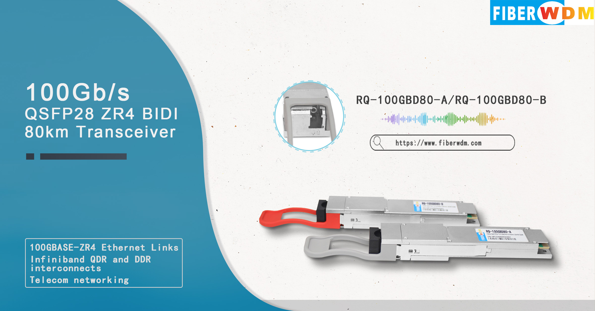
100Gb/s QSFP28 ZR4 BIDI シングルファイバー 80km トランシーバー
RQ-100GBD80-A/RQ-100GBD80-B

FIBERWDM の RQ-100GBD80-A/RQ-100GBD80-Bは、100G 80km シングルファイバー光通信アプリケーション向けに設計されています。このモジュールには、4 レーン光送信機、4 レーン光受信機、および 2 線シリアル インターフェイスを含むモジュール管理ブロックが含まれています。光信号は、業界標準の LC コネクタを介してシングルモード ファイバーに多重化されます。ブロック図を図 1 に示します。
電気的特性
以下の電気的特性は、特に指定がない限り、推奨動作環境に基づいて定義されます。
パラメータ |
シンボル |
分。 |
タイプ |
マックス |
ユニット |
ノート |
消費電力 |
p |
|
|
5.5 |
わ |
|
供給電流 |
ICC |
|
|
1585 |
ミリアンペア |
|
|
||||||
入力差動インピーダンス |
リン |
|
100 |
|
Ω |
|
差動終端の不一致 |
|
|
|
10 |
% |
|
差動データ入力振幅 |
ヴィン、PP |
180 |
|
1000 |
ミリボルト |
|
LPMode、リセット、ModSelL |
ヴィル |
-0.3 |
|
0.8 |
五 |
|
VIH |
2 |
|
Vcc+0.3 |
五 |
|
|
受信機 |
||||||
差動データ出力振幅 |
ヴォート、PP |
350 |
|
900 |
ミリボルト |
|
差動終端の不一致 |
|
|
|
10 |
% |
|
移行時間、20~80% |
|
9.5 |
|
|
追伸 |
|
ModPrsL と IntL |
巻 |
0 |
|
0.4 |
五 |
|
ヴォー |
Vcc-0.5 |
|
Vcc+0.3 |
五 |
|
|
光学特性
以下の光学特性は、特に指定がない限り、推奨動作環境下で定義されます。
パラメータ |
シンボル |
分。 |
典型的な |
マックス |
ユニット |
ノート |
||
送信機 |
||||||||
車線波長(範囲) |
RQ-100GBD80-A |
0 0 |
1272.55 |
1273.55 |
1274.54 |
ナノメートル |
|
|
L1 |
1276.89 |
1277.89 |
1278.89 |
ナノメートル |
|
|||
L2 |
1281.25 |
1282.26 |
1283.27 |
ナノメートル |
|
|||
L3 |
1285.65 |
1286.66 |
1287.68 |
ナノメートル |
|
|||
RQ-100GBD80-B |
L4 |
1294.53 |
1295.56 |
1296.59 |
ナノメートル |
|
||
L5 |
1299.02 |
1300.05 |
1301.09 |
ナノメートル |
|
|||
L6 |
1303.54 |
1304.58 |
1305.63 |
ナノメートル |
|
|||
L7 |
1308.09 |
1309.14 |
1310.09 |
ナノメートル |
|
|||
信号速度、各車線 |
|
|
25.78125 |
28.05 |
ギガビット/秒 |
|
||
サイドモード抑制比 |
SMSR |
30 |
|
|
|
|
||
総発射パワー |
PT |
8.0 |
|
10.5 |
dBm |
|
||
各レーンの平均発射力 |
平均 |
2.0 |
|
4.5 |
dBm |
|
||
消光比 |
緊急 |
6.0 |
|
|
デシベル |
|
||
2 つのレーン間の発射力の差 (OMA) |
Ptx、差分 |
|
|
3.6 |
デシベル |
|
||
各レーンのOFF送信機の平均発射電力 |
ポフ |
|
|
-30 |
dBm |
|
||
送信機反射率 |
RT |
|
|
-12 |
デシベル |
|
||
リン20OMA |
リン |
|
|
-130 |
dB/Hz |
|
||
光リターンロス許容範囲 |
トル |
|
|
20 |
デシベル |
|
||
送信機アイマスク {X1、X2、X3、Y1、Y2、Y3} |
|
{0.25、0.4、0.45、0.25、0.28、0.4} |
|
|
||||
受信機 |
||||||||
車線波長(範囲) |
RQ-100GBD80-A
|
0 0 |
1294.53 |
1295.56 |
1296.59 |
ナノメートル |
|
|
L1 |
1299.02 |
1300.05 |
1301.09 |
ナノメートル |
|
|||
L2 |
1303.54 |
1304.58 |
1305.63 |
ナノメートル |
|
|||
L3 |
1308.09 |
1309.14 |
1310.09 |
ナノメートル |
|
|||
RQ-100GBD80-B |
L4 |
1272.55 |
1273.55 |
1274.54 |
ナノメートル |
|
||
L5 |
1276.89 |
1277.89 |
1278.89 |
ナノメートル |
|
|||
L6 |
1281.25 |
1282.26 |
1283.27 |
ナノメートル |
|
|||
L7 |
1285.65 |
1286.66 |
1287.68 |
ナノメートル |
|
|||
信号速度、各車線 |
|
|
25.78125 |
28.05 |
ギガビット/秒 |
|
||
各レーンの平均受信電力 |
|
-30 |
|
-7 |
dBm |
|
||
受信電力(OMA)、各レーン |
|
|
|
-7 |
dBm |
|
||
受信機の反射率 |
|
|
|
-26 |
デシベル |
|
||
受信感度 平均、各レーン |
セン1 |
|
|
-22 |
dBm |
1 |
||
SEN2 |
|
|
-21 |
dBm |
2 |
|||
SEN3 |
|
|
-28 |
dBm |
3 |
|||
SEN4 |
|
|
-27 |
dBm |
4 |
|||
LOSアサート |
ロサ |
-40 |
|
|
dBm |
|
||
LOS アサート解除 |
LOSD |
|
|
-29 |
dBm |
|
||
LOSヒステリシス |
ロッシュ |
0.5 |
|
|
デシベル |
|
||
ノート:
1. 25.78125Gbps、ER=8.2dB、BER=<1E-12、PRBS=2³¹-1 NRZで測定
2. 28.05Gbps、ER=8.2dB、BER=<1E-12、PRBS=2³¹-1 NRZで測定
3. 25.78125Gbps、ER=8.2dB、BER=<5E-5、PRBS=2³¹-1 NRZで測定
4. 28.05Gbps、ER=8.2dB、BER=<5E-5、PRBS=2³¹-1 NRZで測定
デジタル診断機能
以下のデジタル診断特性は、特に指定がない限り、通常の動作条件に基づいて定義されます。
パラメータ |
シンボル |
分。 |
マックス |
ユニット |
範囲 |
温度モニター絶対誤差 |
DMI_温度 |
-3 |
3 |
℃ |
-40〜85℃ |
電源電圧モニター絶対誤差 |
DMI_VCC |
-3 |
3 |
% |
0~Vcc |
RXパワーモニター絶対誤差 |
DMI_RX |
-3 |
3 |
デシベル |
-7~-30dBm |
バイアス電流モニターエラー |
DMI_バイアス |
-10 |
10 |
% |
0〜120mA |
TXパワーモニター絶対誤差 |
DMI_TX |
-3 |
3 |
デシベル |
2~4.5dBm |
絶対最大定格
It has to be noted that the operation in excess of any individual absolute maximum ratings might cause permanent damage to this module.
Parameter |
Symbol |
Min |
Max |
Unit |
Notes |
Storage Temperature |
TS |
-40 |
85 |
℃ |
|
Power Supply Voltage |
VCC |
-0.3 |
4.0 |
V |
|
Relative Humidity (non-condensation) |
RH |
15 |
85 |
% |
|
Damage Threshold |
THd |
6.5 |
|
dBm |
|
Recommended Operating Conditions
Parameter |
Symbol |
Min |
Typical |
Max |
Unit |
Notes |
Operating Case Temperature |
TOP |
0 |
|
70 |
℃ |
Commercial |
-5 |
|
85 |
℃ |
Extended |
||
-40 |
|
85 |
℃ |
Industrial |
||
Power Supply Voltage |
VCC |
3.135 |
3.3 |
3.465 |
V |
|
Data Rate, each Lane |
|
|
25.78125 |
28.05 |
Gb/s |
|
Control Input Voltage High |
|
2 |
|
Vcc |
V |
|
Control Input Voltage Low |
|
0 |
|
0.8 |
V |
|
Link Distance (SMF) |
D |
|
|
80 |
km |
1 |
Notes:
1. Depending on actual fiber loss/km (link distance specified is for fiber insertion loss of 0.35dB/km)
ModSeIL
The ModSelL is an input pin. When held low by the host, the module responds to 2-wire serial communication commands. The ModSelL allows the use of multiple modules on a single 2-wire interface bus. When the ModSelL is "High", the module shall not respond to or acknowledge any 2-wire interface communication from the host. ModSelL signal input node shall be biased to the "High" state in the module.
In order to avoid conflicts, the host system shall not attempt 2-wire interface communications within the ModSelL de-assert time after any modules are deselected. Similarly, the host shall wait at least for the period of the ModSelL assert time before communicating with the newly selected module. The assertion and de-asserting periods of different modules may overlap as long as the above timing requirements are met.
ResetL:
The ResetL pin shall be pulled to Vcc in the module. A low level on the ResetL pin for longer than the minimum pulse length (t_Reset_init) initiates a complete module reset, returning all user module settings to their default state. Module Reset Assert Time (t_init) starts on the rising edge after the low level on the ResetL pin is released. During the execution of a reset (t_init) the host shall disregard all status bits until the module indicates a completion of the reset interrupt. The module indicates this by asserting "low" an IntL signal with the Data Not_Ready bit negated. Note that on power up (including hot insertion) the module should post this completion of reset interrupt without requiring a reset.
LPMode:
LPMode: The LPMode pin shall be pulled up to Vcc in the module. The pin is a hardware control used to put modules into a low power mode when high. By using the LPMode pin and a combination of the Power override, Power_set and High_Power_Class_Enable software control bits (Address A0h, byte 93 bits 0,1,2).
ModPrsL:
ModPrsL is pulled up to Vcc_Host on the host board and grounded in the module. The ModPrsL is asserted "Low" when inserted and deasserted "High" when the module is physically absent from the host connector.
IntL:
IntL は出力ピンです。IntL が「Low」の場合、モジュールの動作障害の可能性またはホスト システムにとって重大なステータスを示します。ホストは、2 線式シリアル インターフェイスを使用して割り込みのソースを識別します。IntL ピンはオープン コレクタ出力であり、ホスト ボード上のホスト電源電圧にプルアップする必要があります。リセットの完了後、バイト 2 ビット 0 (データ準備完了) が値 '0' で読み取られ、フラグ フィールドが読み取られると、INTL ピンは「High」にアサート解除されます。
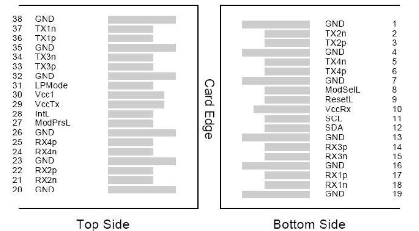
ピンの割り当てと説明

図1. ホストボードコネクタブロックのピン番号と名前の図
ピン |
シンボル |
名前/説明 |
ノート |
1 |
グランド |
送信機グランド(受信機グランドと共通) |
1 |
2 |
送信 |
送信機反転データ入力 |
|
3 |
送信 |
トランスミッタ非反転データ出力 |
|
4 |
グランド |
送信機グランド(受信機グランドと共通) |
1 |
5 |
送信 |
送信機反転データ入力 |
|
6 |
翻訳: |
トランスミッタ非反転データ出力 |
|
7 |
グランド |
送信機グランド(受信機グランドと共通) |
1 |
8 |
モッドセル |
モジュール選択 |
|
9 |
リセットL |
モジュールのリセット |
|
10 |
受信電圧 |
3.3V電源レシーバー |
2 |
11 |
SCL |
2線式シリアルインターフェースクロック |
|
12 |
SDA |
2線式シリアルインターフェースデータ |
|
13 |
グランド |
送信機グランド(受信機グランドと共通) |
|
14 |
受信3p |
レシーバ非反転データ出力 |
|
15 |
受信3n |
受信機反転データ出力 |
|
16 |
グランド |
送信機グランド(受信機グランドと共通) |
1 |
17 |
受信1p |
レシーバ非反転データ出力 |
|
18 |
受信1n |
受信機反転データ出力 |
|
19 |
グランド |
送信機グランド(受信機グランドと共通) |
1 |
20 |
グランド |
送信機グランド(受信機グランドと共通) |
1 |
21 |
受信2n |
受信機反転データ出力 |
|
22 |
受信2p |
レシーバ非反転データ出力 |
|
23 |
グランド |
送信機グランド(受信機グランドと共通) |
1 |
24 |
受信4n |
受信機反転データ出力 |
1 |
25 |
受信4p |
レシーバ非反転データ出力 |
|
26 |
グランド |
送信機グランド(受信機グランドと共通) |
1 |
27 |
モッドPrsl |
モジュールあり |
|
28 |
国際 |
割り込み |
|
29 |
VccTx |
3.3V電源トランスミッター |
2 |
30 |
Vcc1 |
3.3V電源 |
2 |
31 |
LPモード |
低電力モード |
|
32 |
グランド |
送信機グランド(受信機グランドと共通) |
1 |
33 |
翻訳: |
トランスミッタ非反転データ入力 |
|
34 |
送信 |
送信機反転データ出力 |
|
35 |
グランド |
送信機グランド(受信機グランドと共通) |
1 |
36 |
TX1p 翻訳 |
トランスミッタ非反転データ入力 |
|
37 |
送信者 |
送信機反転データ出力 |
|
38 |
グランド |
送信機グランド(受信機グランドと共通) |
1 |
ノート:
1. GND は、QSFP28 モジュールに共通する信号と供給 (電源) のシンボルです。QSFP28 モジュール内ではすべて共通であり、特に明記しない限り、すべてのモジュール電圧はこの電位を基準とします。これらをホスト ボードの信号共通グランド プレーンに直接接続します。
2. VccRx、Vcc1、VccTx は受信および送信電源であり、同時に適用する必要があります。推奨されるホスト ボード電源フィルタリングを以下に示します。Vcc Rx、Vcc1、Vcc Tx は、QSFP28 トランシーバー モジュール内で任意の組み合わせで内部接続できます。コネクタ ピンはそれぞれ最大電流 1000mA の定格です。
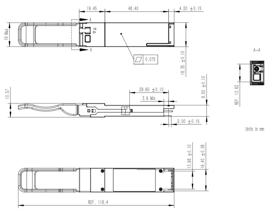
機械寸法

図2. 機械概要
注文情報
部品番号 |
製品説明 |
RQ-100GBD80-A |
100G QSFP28 BIDI トランシーバー、TX1273.55/1277.89/1282.26/1286.66nm/RX1295.56/1300.05/1304.58/1309.14nm、シンプレックス LC、80km、0~+70°C、DDM 付き |
RQ-100GBD80-B |
100G QSFP28 BIDI トランシーバー、TX1295.56/1300.05/1304.58/1309.14nm/RX1273.55/1277.89/1282.26/1286.66nm、シンプレックス LC、80km、0~+70°C、DDM 付き |
この製品について知りたいですか?
あなたは私達のプロダクトに興味があり、詳細を知りたいのですが、ここにメッセージを残してください