分散とOSNR
Jul 23, 20241. OSNR
1)The OSNR is defined as the ratio of optical signal power and noise power in the optical effective bandwidth of 0.1nm. The power of the optical signal is generally taken as the peak value, and the power of the noise is generally taken as the power level of the middle point of the two-phase flow path.
2)The WDM system is essentially an OSNR restricted system, and the transmission distance is limited by OSNR. OSNR is calculated as follows:

3)OSNR can only be increased by increasing P and decreasing NF;
Improve P: use high-power BA and OLA, but limited by nonlinear effects;
Reducing NF: using Raman amplifier;
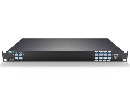
Guangzhou Ruidong Company FiberWDM self-developed optical amplifiers BA,PA,OLA, these three amplifiers have the characteristics of flat gain, low noise index, BA is often used in the sending end of the system to improve the optical power of the system; OLA is often used in the trunk section of the line to compensate for the loss of optical power on the line. PA is usually used at the receiving end of the system to improve the received optical power of the system.
2. Dispersion of optical fibers
1)The different frequencies or modes in the optical pulse have different group speeds in the fiber, so these frequency components and modes reach the end of the fiber first and then, making the optical pulse widening, which is the dispersion of the fiber.
2)The permissible range of dispersion wavelength is 1300nm to 1324nm. The dispersion coefficient in the 1550nm window is positive. At wavelength 1550nm, the typical value of the dispersion coefficient D is 17ps/nm-km, and the maximum value is generally not more than 20ps/nm-km.
3)Dispersion widens or compresses the signal pulse, resulting in signal intensity distortion. Dispersion causes the light pulses between different wavelength channels to diverge, reducing the FWM and XPM effects (SPM refers to self-phase modulation, XPM refers to cross-bit modulation).
Dispersion typical value
G.652:17ps/nm/km;
G.653:0ps/nm/km;
G.655:4-6 or 8-9ps/nm/km;
4)Dispersion compensation
The dispersion compensation principle is as follows:
(1) 1 km DCM compensation 1 km optical cable;
(2) In the optical discharge station as far as possible not to fill, even if the overfill is controlled within 400ps/nm: in the optical discharge station underfill control within 2400ps/nm;
(3) The residual dispersion at the terminal station is controlled within 400-800ps/nm;
(4) G.652 fiber optic cable dispersion project budget is 20ps/(nm·km);
(5) The G.655 optical cable dispersion project budget is 4.5ps/(nm·km);
広州瑞東ファイバーWDMが開発したDCM分散補償モジュールは、成熟した信頼性の高い光ファイバープロセスを備え、挿入損失が低く、さまざまなパッケージングスタイル、コネクタタイプ、ジャンパー長を提供でき、Cバンドの標準シングルモードファイバー(G.652)の分散と分散スロープを補償できるため、光伝送システムの性能が向上します。

住所 : Room 901, Building 6, JD Smart Industrial Park, No. 128, Juhua Stone Avenue, Huashan Town, Huadu District, Guangzhou City
電話 : +86 15989256178
Whatsapp : +86 15914235380
メール : sales@fiberwdm.com